District Sales Manager
Email: steve.buck@newmill.com
Phone: 870.925.0660
Main Title
Subhead
Text if needed
Second Column
Test
Title
There are many variations of passages of Lorem Ipsum available, but the majority have suffered alteration in some form, by injected humour, or randomised words which don’t look even slightly believable. If you are going to use a passage of Lorem Ipsum.
There are many variations of passages of Lorem Ipsum available, but the majority have suffered alteration in some form, by injected humour, or randomised words which don’t look even slightly believable. If you are going to use a passage of Lorem Ipsum.
Test
sdgsdgsdg
Test
Test
Test
Flyout demo
Featured Projects




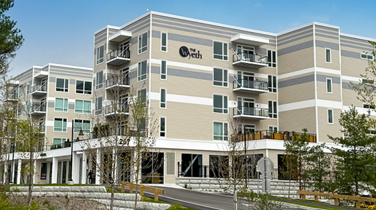



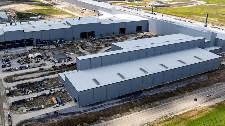


Under-Flange (UF) Connections
| Connection Number | Max. Girder Flange Width (in) Width | Min. Girder Depth | Min. Joist Depth | Max. Joist Vertical LRFD Reaction (kips) | Number of Bolts | Bolt Diam. (in) | Bolt Grade ASTM | Hole Diam. in Joist End Plate (in) | Slot Width in Shear Tab (in) | Slot Length in Shear Tab (in) | Connection Drawing |
|---|---|---|---|---|---|---|---|---|---|---|---|
| NMUFC-1 | 11.50 | 16 | 18 | 62 | 3 | 1.00 | A490-N | 1.125 | 1.125 | 1.3125 | NMUFC-1.pdf |
| NMUFC-1A | 17.50 | 16 | 18 | 62 | 3 | 1.00 | A490-N | 1.125 | 1.125 | 1.3125 | NMUFC-1A.pdf |
| NMUFC-2 | 11.50 | 18 | 18 | 97 | 4 | 1.00 | A490-N | 1.125 | 1.125 | 1.3125 | NMUFC-2.pdf |
| NMUFC-2A | 17.50 | 18 | 18 | 97 | 4 | 1.00 | A490-N | 1.125 | 1.125 | 1.3125 | NMUFC-2A.pdf |
| NMUFC-3 | 11.50 | 21 | 18 | 145 | 4 | 1.25 | A490-N | 1.375 | 1.375 | 1.625 | NMUFC-3.pdf |
| NMUFC-3A | 17.50 | 21 | 18 | 145 | 4 | 1.25 | A490-N | 1.375 | 1.375 | 1.625 | NMUFC-3A.pdf |
Extended-Tab (ET) Connections
| Connection Number | Max. Girder Flange Width (in) Width | Min. Girder Depth | Min. Joist Depth | Max. Joist Vertical LRFD Reaction (kips) | Number of Bolts | Bolt Diam. (in) | Bolt Grade ASTM | Hole Diam. in Joist End Plate (in) | Slot Width in Shear Tab (in) | Slot Length in Shear Tab (in) | Connection Drawing |
|---|---|---|---|---|---|---|---|---|---|---|---|
| NMETC-1 | 11.50 | 18 | 18 | 26 | 3 | 1.00 | A490-N | 1.125 | 1.125 | 1.3125 | NMETC-1.pdf |
| NMETC-2 | 11.50 | 21 | 20 | 47 | 4 | 1.00 | A490-N | 1.125 | 1.125 | 1.3125 | NMETC-2.pdf |
| NMETC-2A | 17.50 | 21 | 20 | 35 | 4 | 1.00 | A490-N | 1.125 | 1.125 | 1.3125 | NMETC-2A.pdf |
| NMETC-3 | 11.50 | 24 | 22 | 90 | 4 | 1.25 | A490-N | 1.375 | 1.375 | 1.625 | NMETC-3.pdf |
| NMETC-3A | 17.50 | 24 | 22 | 65 | 4 | 1.25 | A490-N | 1.375 | 1.375 | 1.625 | NMETC-3A.pdf |
| NMETC-4 | 11.50 | 30 | 26 | 114 | 5 | 1.25 | A490-N | 1.375 | 1.375 | 1.625 | NMETC-4.pdf |
| NMETC-4A | 17.50 | 30 | 26 | 100 | 5 | 1.25 | A490-N | 1.375 | 1.375 | 1.625 | NMETC-4A.pdf |
| NMETC-5 | 11.50 | 33 | 30 | 136 | 6 | 1.25 | A490-N | 1.375 | 1.375 | 1.625 | NMETC-5.pdf |
| NMETC-5A | 17.50 | 33 | 30 | 136 | 6 | 1.25 | A490-N | 1.375 | 1.375 | 1.625 | NMETC-5A.pdf |
DESIGN RESPONSIBILITY NOTICE: Our published set of standards for flush-frame connections are provided as design aids to expedite the design and coordination of open-web steel joists with flush-framed connections to wide-flange girders. The project engineer of record (EOR) is solely responsible for the design of the structure, the specification of the joists, and the selection of appropriate connections between the joist and wide-flange girder. To that end, these details may be used as-is or adapted by the EOR as appropriate to the specific project conditions, including the size of the beam shear tab, size of bolts, grade of bolts, quantity of bolts, and weldment of beam tab plate to the wide-flange girder with appropriate weld size proportionate to the web thickness of the wide-flange girder. New Millennium provides design calculations for each standard connection detail for the EOR to use in validating strength and assessing appropriateness to the specific project. New Millennium is not responsible for verifying whether these connection designs are appropriate for use in any given condition on any given project.
fhjakshfjksfjksdnf

gmsdkngksdngkesngksn
fhawifhiahfiueshfi
sfdsfgdsgds
fhjieshfisehfif
duishdiuahfiuhfiuH
FAUHFUIAhfuihIHU
District Sales Manager
Email: michael.caywood@newmill.com
Phone: 803.540.2206